Assembly guide and manufacturing manual
Please do not assemble or try manufacturing the meter if you are not a skilled electronics engineer or engineer with similar skill.
This document summarizes the manufacturing guide to enable a skilled person to manufacture the smart energy meter. The foldered is structured as highlighted below including informations available in each folder.
Hardware manufacturing
The hardware is splitted into different parts as highlighted below.
- Extracting manufacturing file.
- Soldering/assembling PCB.
- Firmware flashing to microcontroller.
Extracting manufacturing file
The first step is to extract the manufacturing/production files from Github in the link provided below https://github.com/EnAccess/OpenSmartMeter/tree/main/hardware/production_files, the zip file is sent to a PCB manufacturing company for the board to be manufactured. The manufactured PCB is shipped back to the design engineer.
Soldering/assembling PCB
The PCB is assembled, soldered according to the components value as labeled on the silkscreen layer of the PCB board.
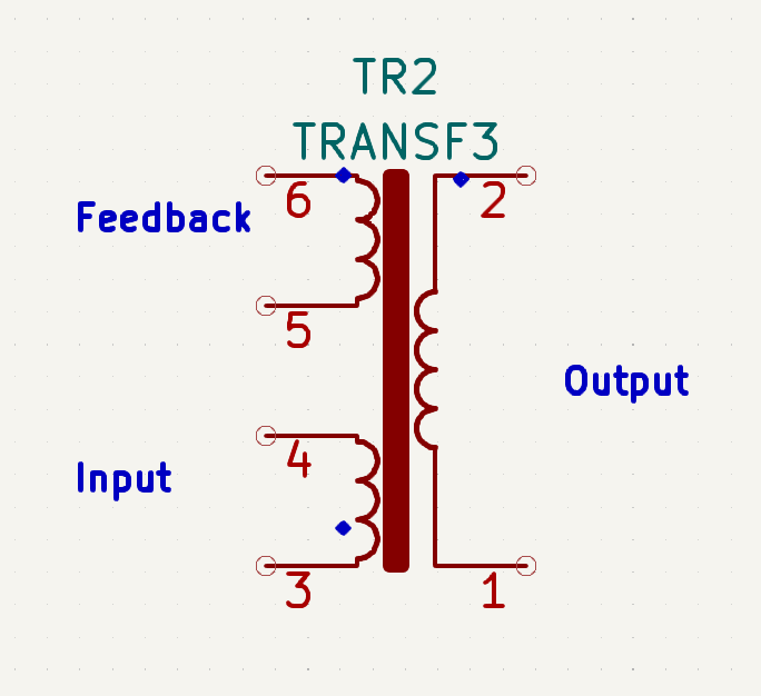
The turn ratio of the ferrite core transformer is given below
- Feedback = 7 turns
- Input (100v - 270v) = 53 turns
- Output(12v) = 10 turns
First trial of the assembly
Step 1: Testing component proper assembling and soldering
After developer is done assembling the components on the PCB, it is advisable to test the PCB first by connecting the battery to the battery connector to test if all connection is correct or not, if all connection is correct the meter LCD will display, then meter boot and try connecting to internet before the LCD is turned off due to unavailability of mains and to preserve battery life.
Step 2: Incandescent bulb test
Connect the input of the meter through an incandescent bulb without any load to the meter to prevent the components from going up in smoke if there is a short or mis-soldering, if the meter PCB is faulty the incandescence bulb will light up brightly, if all is ok, the meter will start up however the bulb may light up a little bit if all is ok.
Step 3: Run the device with selftest firmware
TBD: Explain in detail, how this is achieved.
Hardware calibration
The meter calibration is done after the meter PCB component is fully assembled alongside exterior casing.
A meter test bench is needed to know the true value of voltage and current to be calibrated into the meter.
Step 1: Calibrating voltage and current
The voltage and current is calibrated by calculating the value measured by meter as compared to the true value measured by a test bench.
-
The excel sheet available in the link provided below is used to calibrate the voltage and current by inputting the measured and actual values of voltage and current in the appropriate cell of the Excel calculator.
-
The HEX code gotten is written to the neccesary registers of
Ugain,IgainNin theSAM_UART.cpplibrary provided here. -
The checksum2 value displayed on the LCD screen while the meter is starting up is written to the CSTwo register in the
SAM_UART.cpplibrary -
design engineer re-uploads the code to the chip and all measuring parameter is correct.
Step 2: Setting impulse rate
The impulse rate is changed by writing to PLconstH and PLconstL in the SAM_UART.cpp library after inputting the correct value of
Un = 240V(measured voltage).Ib = 5A(base current).GL = 1(line current circuit gain).VL = 21.3(sampling voltage of current circuit inMV).VU = 260(sampling voltage of voltage circuit inMV).MC = 2000(impulse rate) Note: the impulse is 1000, however the value is multiplied by 2 due to current scaling.
The values specified above is the values used according to the resistor value used in meter PCB.
Step 3: Calibrating impulse
A test bench is required to measure the % error of the meter, after this is done the design engineer can input the error gotten into the Excel calculator. After the error is calculated, the design engineer write the value gotten for Lgain and Igain to the neccesary register in the SAM_UART.cpp library, then the new value of checksum1 is rewritten to the library for the meter to blink properly.
Firmware flashing to microcontroller
These steps are old and need to be adapted to PlatformIO deployment of the firmware.
the first thing to do is to Install STM32 Add-on to Arduino IDE by following the steps below.
Step 1: Prepare Arduino development environement
Add the URL below to Additional Board Manager URLs text box
https://github.com/stm32duino/BoardManagerFiles/raw/master/STM32/package_stm_index.json

Go to Tools > Board > Boards Manager

Search for STM32, select latest version and click Install

Step 2: Installing STM32CubeProg
Follow the instructions below to install STM32CubeProg to your computer
Download and install STM32CubeProg from ST.com: https://www.st.com/en/development-tools/stm32cubeprog.html

Step 3: Flashing firmware to microcontroller using USB to 3.3V TTL adapter (Windows only)
Wiring : Follow the wiring digram below to connect the STM32 Blue Pill to USB to 3.3V TTL adapter


Make sure the boot 0 jumper pin on the board is set to 1 (programming mode) while uploading the boot loader. Once the boot loader is flashed this pin can be changed back to initial position (operating mode).
Step 4: Setup Arduino IDE
Set the Upload method to STM32CubeProgrammer (Serial)

Follow the configuration setting below to upload sketch

STM32 Operating and programming

Things to consider in firmware deployment
There are some hardcoded variables in the firmware code which needs to be in sync with the values used on the web server e.g token, API key,web server. sample pictures of variables to be changed is shown below.
// defines
#define TOKEN "5GBw6kqNCN93BN3nuuvJ"  //"YOUR_ACCESS_TOKEN"
#define THINGSBOARD_SERVER "demo.thingsboard.io"
#define THINGSBOARD_PORT 80
const char server[] =
    "paygotesting.000webhostapp.com";  // domain name: example.com,
                                       // maker.ifttt.com, etc
const char resource[] =
    "/subscribe.php";  // resource path, for example: /post-data.php
const int port = 80;   // server port number
HttpClient http(client, server, port);
String apiKeyValue = "tPmAT5Ab3j7F9";
More information as relating to the implementation of the firmware with the software is available in https://enaccess.github.io/OpenSmartMeter/docs/firmware/
Web Software
The web software is split into different parts as highlighted below.
- Extraction of zip file from Github.
- Creating database.
- Linking ThingsBoard public link to webpage.
Extraction of file from Github
The web software can be replicated by any developer by downloading the code file from https://github.com/EnAccess/OpenSmartMeter/tree/main/web_software . After the code is downloaded, developer will need to host the web on a hosting platform.
Creating database
The database schema file can be downloaded from the Github link provided below https://github.com/EnAccess/OpenSmartMeter/blob/main/web_software/database_seed/meter.sql for testing purpose, next user can assign a meter number as desired from MT1 to MT99990 and insert into the meter Database column for meter number. Developer need to change password and database name in web code to same password and database name as created by developer to enable access to the database.
Linking ThingsBoard public link to webpage
After ThingsBoard page is setup, developer make the data available by changing the privacy setting from private to public, next the public link is copied to the ThingsBoard column specified in the database for each user.
Things to consider in software/API deployment
There are some variables that needs to be changed in the backend codes, the database details need to be changed to the databases details as created on the webserver. More information as relating to the implementation of the software/API deployment is available in https://enaccess.github.io/OpenSmartMeter/docs/backend/